Testing of sBitx at HF Signals
This a document of the current process of testing the sBitx before they are shipped. From 1st May, 2023 onwards, all the sBitxs shipped will carry the test report.
Do not try this at home. You will need a dummy load and an oscilloscope with 50 MHz bandwidth and a signal generator to try it by yourself.
Setting the the test bench
1 The power supply should be on 13.8v, connect mic, and key paddle
2 Set Antuino (signal generator) to 7035, set the wweep 1 KHz to be 1 KHz wide. The signal source should be from another power supply to prevent signal leakage via power cables.
3 Connect Antuino to the other side of the dummy load with at least 60 db Attenuation (50 ohms in series with 100K resistor).
4 A PC/laptop and the sbitx to an ethernet hub before switching on the radio.
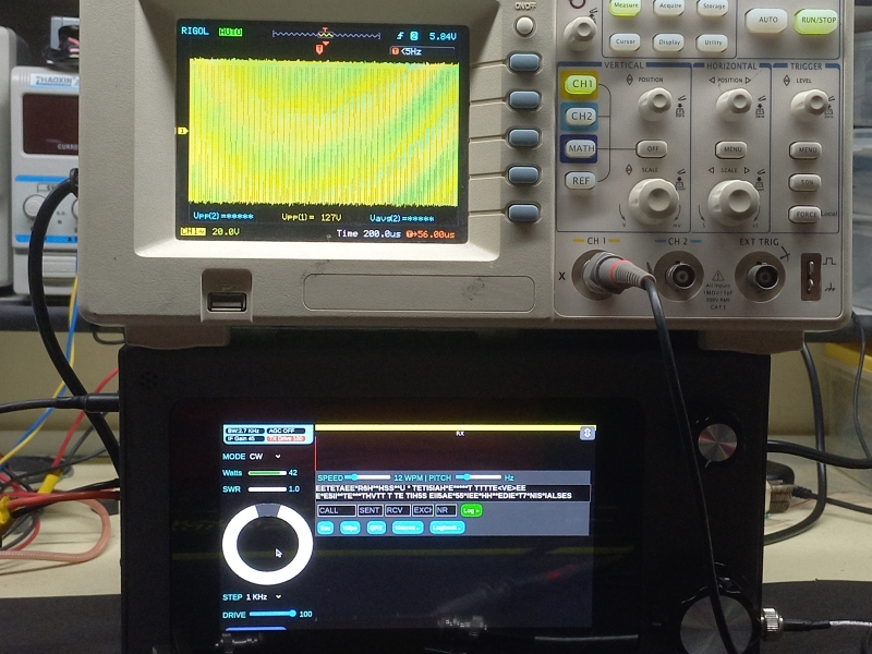
5. Set the Oscilloscope, to 200 uSec/horizontal division, 20v/vertical division rang. Connect the probe across the dummy load.
1. Initial test
1 Switch on the set,
2 Connect dummy load, oscilloscope, other side of dummy to antuino
3 Power on the radio
4 ssh into the radio, they default userid is pi and the password is hf12345
5 run ntpstat, if not synchronized, run
sudo apt install ntp
sudo apt install ntpdate
sudo ntpdate -u time.nist.gov
Type ntpstat until it says the time is synchronized
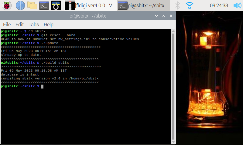
6 get the latest version of sbitx from the github
git reset --hard
 ./update
 ./build sbitx
7 Note the DC Idling current, start sbitx from the ssh command line
8 Check that the RTC clock is detected (look for the message in the Terminal window)
9 Check that the RTC clock is synchronized (this needs active internet) (look for the message in the Terminal window)
10. Note the DC current consumption of the radio in receive mode.
Receive test
1 Tune the Antuino/Signal generator to 7035
2. set RF gain to maximum
3 Set frequency of sbitx to 7035,
4. AGC OFF
5. Is the noise grass visible yes/no
6. Note the signal level on the spectrum display. Each horizontal division is 10 dB. What is the Antuino sweep level above the noise floor? The -65 dBm signal from through the dummy load should still be at least 60 dB above the noise floor.
8.9 Check the earphone audio of sweep. The audio should be clear and distortion free.
PA bias current
1 Set Mode toUSB
2 Set Mic to 1
3 Set Drive to 1
4 Set PA_BIAS1 preset to zero (fully counter-clockwiseBias)
5 Note DC current on PTT
6.. Slowly increase the bias current until the total current consumed by teh radio is increased by approximately 250 mA.
Bridge calibration.
We first check to see if the bridge is already calibrated and if it isn’t we will proceed with the calibration
1 Set Mode to CW
2 Set Freq to 7035 KHz
3 Set CW INPUT to straight key
4 Set Drive to 1
5 Press the PTT and increase the drive gradually to bring up to the RF voltage on the across the dummy to load to read 125 v peak to peak (or, 62 volts peak).
6. Check the power reading on sbitx screen. If power is between 35 and 45 watts, skip the Part B
PartB : Setting the SWR bridge to correct reading
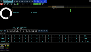
7. Open console panel
8. Enter “metercal” (DO NOT TOUCH ANY OTHER CONTROL ON SCREEN)
9. Press PTT, note that the output as shown on the oscilloscope is still between 120v and 130 v peak to peak RF
10 Adjust function knob until the power reading is 40 watts on sbitx screen.
11 Press the function knob once, change the mode to trigger saving the configuration.
Band Power calibration
1 Keep the dummy load inserted as before, with the oscilloscope probe connected across it.
2 Open the sbitx console panel
3 Enter “txcal”
4 Watch the screen show the power being gradually increased to the correct levels on all bands
6 Delete the wifi connection or take off the ethernet
7. Switch off the sBitx and switch it back again for the next test (two tone test)
Two tone test (switch it on, without Ethernet)
1 Select MODE 2TONE
2 Set frequency to 7035
3 Set Drive to 100
4 Press PTT
5 See the oscilloscope for perfect shape, (no flat top, no underflow)
6. Power output
7 Measure the output with Drive 100 on all bands, on each band. To prevent aliasing perform all transmit tests at 35 KHz from the band edge.
RTC check (after booting it without the Internet)
Check that the RTC time on sbitx screen is same as utctime.net (on phone)
Hardware check
1 Set mode to USB,
2 Mic gain to 25,
3 Frequency on 7043 freq
4 Speak into the mic, note the peak voltage
5 Remove mic
6 Set mic gain to 50
7 Speak into the mic and note the RF
8. From settings panel, Change mode to cw, cwinput to Iambic paddle
9. Test dots and dashes
RF power stress tests
- et the drive to maxium, mode to CW and frequency to 7035 KHz
- Press the PTT and transmit the full carrier for 30 seconds
- Disconnect the PA dummy load and transmit for for 10 seconds with antenna connector open.
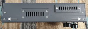
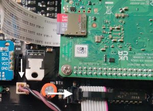
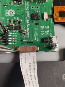
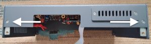
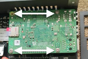
 Now you can access the Raspberry Pi and the other modules. Proceed further only if you plan to remove the PCB from the enclosure.
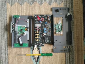 10. To put everything back together, follow this guide in reverse.