Upgrading to switching regulator (Development Edition)
From Anthony Good, K3NG, Anil Rayporula, VU2DXA
The very early sBitx (Developer Edition) were shipped with a linear regulator, the LM338 to drop the voltage down from 13.8V power supply to the 5V needed by the Raspberry Pi and other digital circuitry. This often led to heating issues. An upgrade kit was shipped to these users. These are the instructions to install it properly.
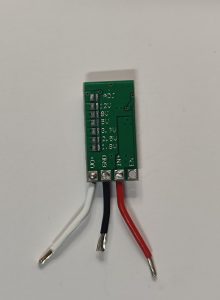
The new regulator looks like this:
1. Take off the top panel and disconnect the speaker. Lay this aside.
2. Disconnect the white ribbon cable going from the Pi to the touch screen display. There are little black tabs on each side of the connector on the display unit that need to pop straight out in the direction of the ribbon cable to release the ribbon cable.
3. Disconnect the brown and black wire (touch display power) from the digital board.
4. Remove the gray ribbon cable out of the digital board by pulling the gray ribbon straight backwards.
5. Loosen the two nuts on the right side holding the metal bracket that the Pi and the digital board is mount to. Do not take the nuts entirely off.
6. Pull the Pi and digital board assembly straight up to remove and set aside.
7. Remove the four screws holding the main board to the chassis
8. Disconnect the two red wires from the power switch on the back panel
9. Remove screws on the four back corners of the outside of the chassis to remove the back panel along with the main board.
10. Put the rest of the chassis with the screen and controls aside. Carefully place the back panel and main board on your workbench and loosen the three screws holding the bar that presses the two final transistors and the LM338 regulator on to the back panel heatsink. Remove the bar and three screws. The main board should be loose from the back panel now.
11. Unsolder the LM338. With the front of the main board facing you, it’s the first three pin device from the left on the back on the back that was against the heatsink.
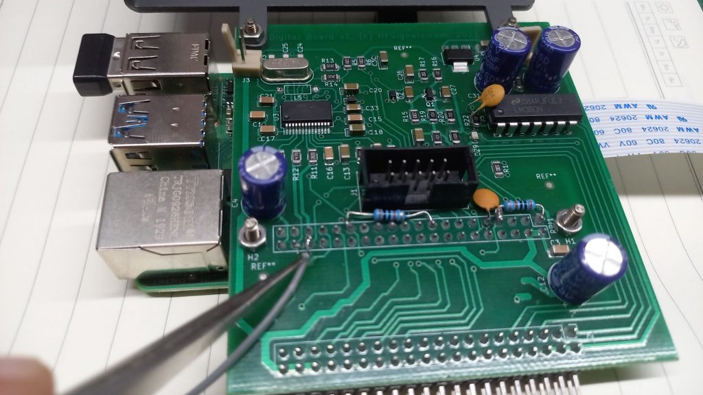
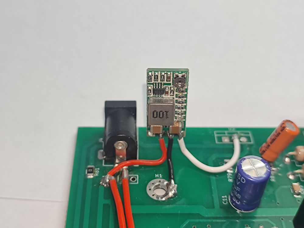
12. Remove the main board screw at H1 and solder the black (ground) wire of the new switching regulator to the ground trace at H1, and replace the screw.
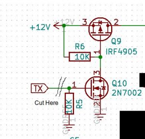
13. Solder the red switching regulator wire (+13.8 volt input) to the right-most pin where the LM338 used to be. This is the input pin shown in the diagram below.
14. Solder the white switch regulator wire (output) to the middle pin, where the LM338 used to be. This is the output pin shown below. (The first pin of the LM338, labeled “Adjust” below, will remain open.
15. Place the main board against the back panel. Place the bar that presses the final transistors to the heatsink place. Place the three screws back in, but do not tighten all the way. Leave them rather loose.
16. Place the main board and back panel together back into the main chassis. Line up the three front jacks (mic, earphone, cw key) to the holes in the front panel. Carefully push the back panel into place until it mates correctly with the side and bottom panels.
17. Line up the main board with the four screw holes. Place the four screws in, starting them, but leaving them slightly loose. After all four are started, tighten all four.
18. Tighten the three screws that are in the bar that presses the two final transistors on to the back panel heatsink. Use your best judgement. (I tightened until the two final transistors would not move with me pressing my finger nail on the side of them.)
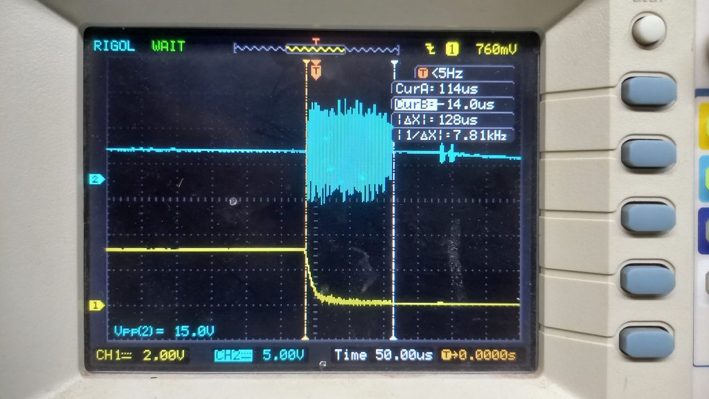
19. (Optional step) Connect the power. Turn on the unit and use a voltmeter to verify that the white lead from the new switching regulator has about 5.4 volts on it. If it is not close to 5.4 volts, stop and troubleshoot. If it’s good, turn off the unit, disconnector the power, and proceed.
20. Re-assemble the remaining parts of the unit. Slide the pi and digital board subassembly back in, being sure to have the pins on the bottom meting correctly with the connector on the main board. Be sure to connect the gray ribbon cable to the back of the digital board (it is keyed so it can be inserted only one way), the white ribbon cable to the display unit (blue side down, silver side out), and black & brown power cable for the display going to the digital board (brown is down, black is up). The assembly manual has pictures that can help (
https://www.hfsignals.com/index.php/sbitx-assembly-manual-v1-0/).
21. Reinstall the top panel, connecting the speaker to the digital board prior to putting the top panel on.
22. Connect the power, and power up!
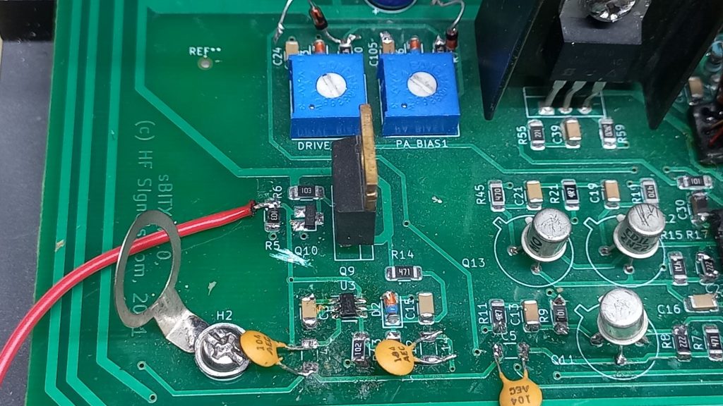
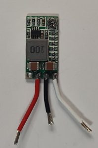
This is how the installed regulator looks (installed on the PCB). It has been photographed outside the box for better clarity.